B Colors, color matching, proof printing – basic concepts
Color is created through the interaction of light, an object, and the eye. The “visible spectrum” contains millions of colors.
Screens and monitors produce colors by means of red, green and blue light (RGB). The light intensities make up a given color. Scanners and digital cameras also work with RGB colors. They read the amounts of red, green, and blue light that are reflected from an image (or transmitted if you scan transparent images). The RGB color space is smaller than the visible spectrum of light. RGB colors are device dependent, they vary with scanner or monitor characteristics.
Color printing is based on the CMYK color space. Cyan, Magenta, Yellow, and Black inks are mixed on paper to produce a given color. The CMYK color space is even smaller than the RGB color space. CMYK colors vary with printer, ink, and paper characteristics.
The CIE (Commission Internationale de l’Eclairage) created different color spaces that specify colors in terms of human perception. One example is the CIELab color space. Lab colors are device independent.
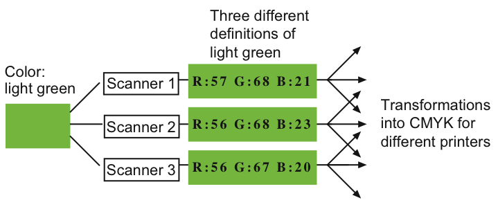
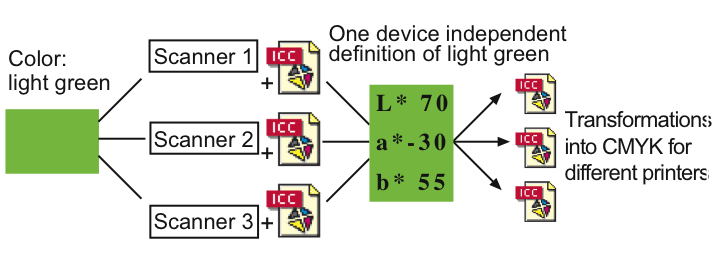
If you want to capture, edit, place, and print an image, you have to transform the scanned RGB values into CMYK values for the output device. This process is called separation. If you want to have predictable color results, you must have calculation models that match RGB to CMYK during separation. As RGB and CMYK values are device dependent, you can never exactly define a color. E.g. capturing one particular color with three different scanners or cameras will produce three different sets of RGB values. Thus, you will have different input values for the transformation into CMYK. You must have a specific transformation table for every possible scanner–printer combination. If you have a device independent color space like Lab, you can exactly define the color you scanned. Considering the color characteristics of the different scanners – which are described in the device profiles (see ICC, ICC profiles in G “Glossary”) – you can transform the different sets of RGB values into one single Lab color definition. Now, you have only one single input value for the transformation into CMYK. Fig. B.1 and Fig. B.2 illustrate the effect of a device independent color space (Please note that you may as well have an RGB device on the output side, e.g. an imagesetter).
- Note:
-
Color matching does not always lead to precise reproduction. Some Lab or RGB colors cannot be printed – some can, but not by every given printer. The color matching module has to make sure that deviations are as small as possible. This can be achieved by gamut mapping (see G “Glossary”).
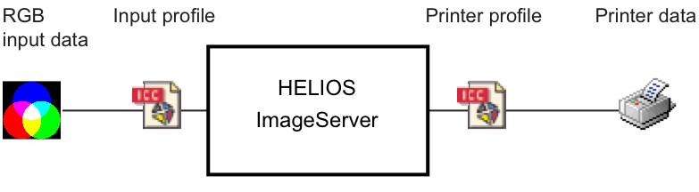
ImageServer is able to transform colors from different color spaces like RGB and CMYK into Lab values and vice versa. Thus, a device independent color space is used for the interchange of color data. The color matching module that is available with ImageServer uses ICC based profiles for color matching.
With ImageServer, the color spaces of single images may be changed as necessary for layout generation and printing. The transformations, however, do not affect the original high-resolution images. These images remain unchanged in terms of color space and file format.
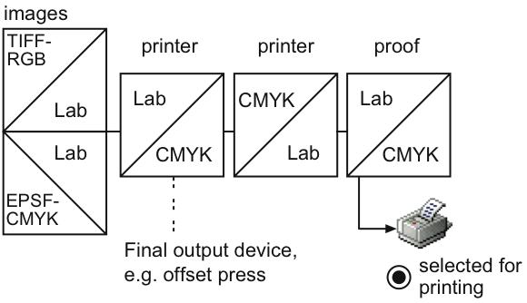
All the color data that can be matched for a printer can also be matched for a proof printer. A proof printer is used to simulate the output results of another printer or a press. The color data transformation and gamut mapping are accomplished for the printer you want to use as final output device (e.g. an offset press). The resulting CMYK values are then transformed into the specific CMYK values of the proof printer. To guarantee a precise simulation, the gamut of the proof printer must not be smaller than that of the printer because there is no gamut mapping from printer to proof. Fig. B.3 shows how color data are transformed if you print to a proof.
With ImageServer, color matching must be activated separately for each printer queue. You have to define a printer profile for your output device and, optionally, a proof profile if you want to simulate your output results on a proof printer. Fig. 4.7 in 4.4 “ICC printer settings” shows the required settings for simulating a newspaper press on a color LaserWriter.
B.1 DeviceLink
ImageServer supports DeviceLink ICC profiles, which are primarily used to convert CMYK colors of one device to CMYK colors of another device, e.g. Euroscale Offset CMYK to gravure printing CMYK. Color conversions using DeviceLink profiles can have properties that are impossible using conventional ICC profiles. Conventional ICC profiles represent color characteristics of color devices (such as scanners, digital cameras, monitors, displays, and printers) and abstract color spaces (such as CIELab). In contrast to conventional ICC profiles, DeviceLink profiles represent direct mappings from one specific color space to another specific color space. Thus, DeviceLink profiles have two color spaces: an input color space and an output color space. Conversions between CMYK color spaces using two conventional ICC profiles have the fundamental disadvantage that the 3 component CIELab space is used as an intermediate step between the input and output 4 component CMYK color spaces. The use of CIELab as an intermediate color space results in the loss of information, which objects should be printed using only the black channel, e.g. black text. Typically conventional conversions from CMYK to CMYK convert Black channel only objects to black objects using Cyan, Magenta and Yellow. Additional ICC profiling software can create DeviceLink profiles for CMYK to CMYK conversions that preserve black channel only objects or which replace Cyan, Magenta and Yellow with Black ink while preserving the color appearance to cut cost and to improve ink drying properties during printing.
The “layout” image conversion tool supports DeviceLink
conversions via the -o DevLinkProfile=mydevlink.icc
option. If a DeviceLink profile is specified, the input image
must have the same color space as the input color space of
the DeviceLink profile. The color space of the output image
is determined by the output color space of the DeviceLink
profile.
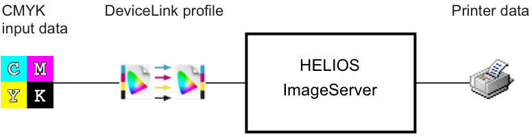
When printing PDFs directly via “pdfprint” or Acrobat plug-in or indirectly via OPI, a DeviceLink profile can be specified within the printer queue. All input color objects with the same color space as the input color space of the DeviceLink profile are color matched using the DeviceLink profile. All other color objects are converted using the input profile and printer profile. Printer queues with DeviceLink profile require a printer profile with the same color space as the output color space of the DeviceLink profile. Assumed that a CMYK printer profile and a CMYK to CMYK DeviceLink profile have been specified, the color data will be:
1. RGB and Lab input data
2. CMYK input data
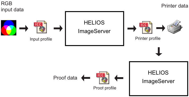
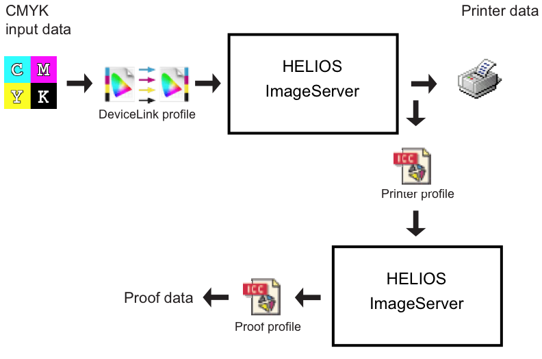
PDF printing, PostScript OPI, and PDF-native OPI using DeviceLink profiles supports proofing, too. Assumed that a CMYK printer profile, a CMYK proof profile and a CMYK to CMYK DeviceLink profile have been specified, the color data will be:
1. RGB and Lab input data
2. CMYK input data
- Note:
-
As specified by the ICC standard, DeviceLink conversions do not have rendering intent support. Rendering intent settings do not alter DeviceLink conversions.
ImageServer includes options to preserve black, white, gray, and primary CMY colors. E.g., with the “Preserve … Colors – Black” option RGB black is detected and converted to CMYK black without Cyan, Magenta, and Yellow. The “Preserve … Colors – CMY” option applies to CMYK to CMYK conversions only and preserves the input color if, and only if black is 0% and exactly one CMY primary color is 100% and all other primary colors are 0%. The preserve color options can be specified separately for raster image data and PDF vector data.
ImageServer supports grayscale ICC profiles, i.e. grayscale images with an ICC profile are properly processed. Grayscale ICC profiles can be specified as printer profiles and as output profiles for image conversions.
BPC is not part of the ICC specifications that have been issued by now. With BPC, the CMM evaluates the lightness range of the used devices and scales between them. Until now, BPC has been available nearly exclusively in some Adobe applications. The BPC option within HELIOS products is available for the Perceptional, Relative Colorimetric and Saturation rendering intents. HELIOS provides the BPC option as 3 additional rendering intents:
4 – for Perceptual with BPC
5 – for Relative Colorimetric with BPC
6 – for Saturation with BPC
Colors converted with BPC are highly source and destination gamut dependent. Some images look better with BPC, others do not. Therefor, it is recommended to check carefully when BPC should be used. However, a refinement of this approach is now available, the Black Plane Compensation.
While the BPC transformation only affects pure gray tones, the Black Plane Compensation in the CMYK color space limits the maximum ink coverage. Therefore, not only pure black is black, but in reality many dots in the vicinity. Thus, not only a single dot is transferred to the target black point, but a whole layer of dots. This means that shadows are still retained, but they appear calmer and less noisy:
7 – for Perceptual with Black Plane Compensation
8 – for Relative Colorimetric with Black Plane Compensation
9 – for Saturation with Black Plane Compensation